Computer Controlled Boom Arm and Track Camera Systems
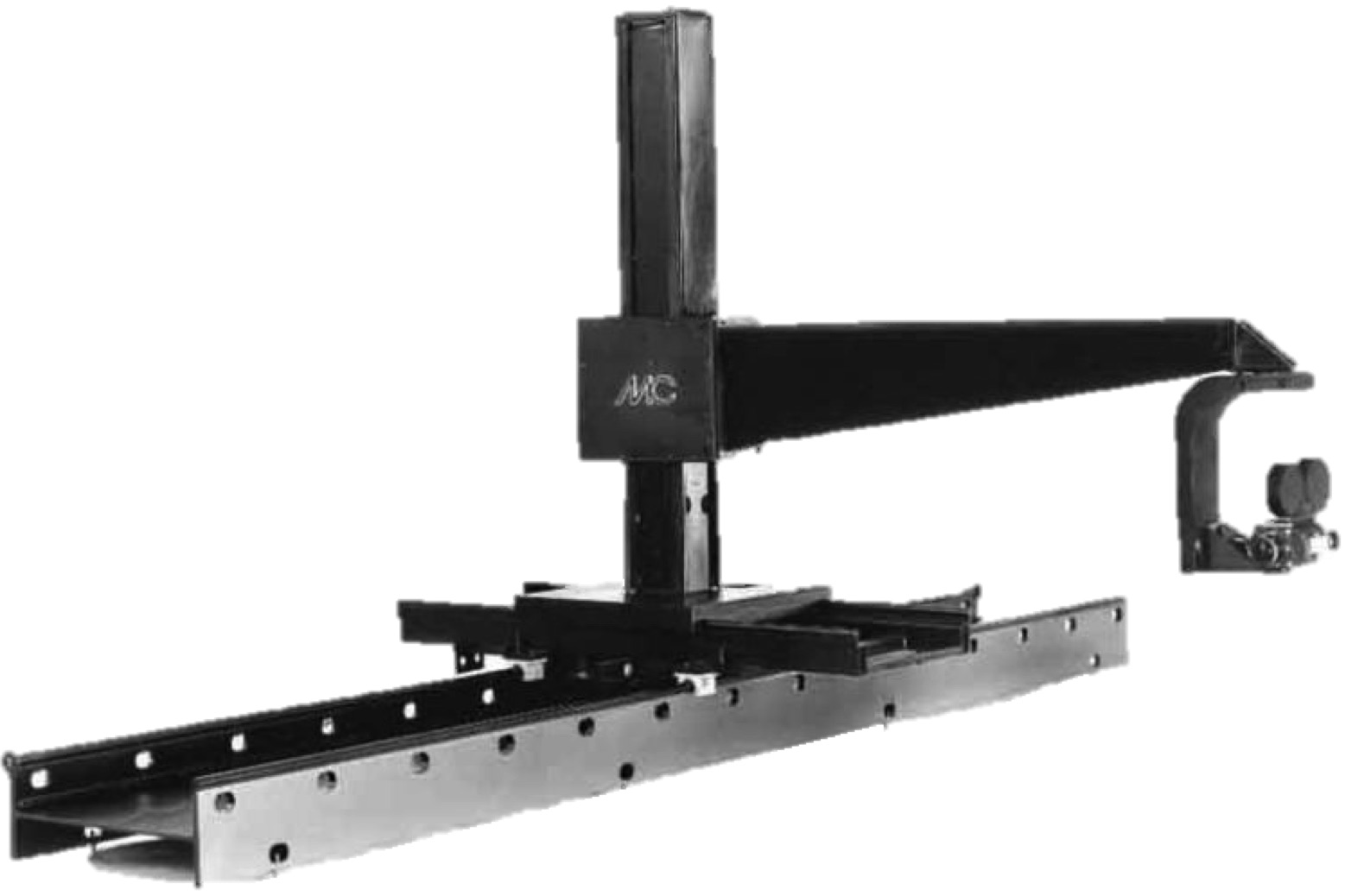
(Above) Standard boom arm system with optional pan/tilt head for customer supplied camera
System shown Includes twenty six foot zoom axis track, heavy duty transmission (servo), six foot east/west track, seven foot north/south column, rotating cube and standard boom extension. All four faces of the cube are intended as mounting surfaces for other accessories. Travels: Zoom axis = 23 feet, east/west axis = 4 feet north/south axis = 5 feet and rotation of the boom axis is infinite. Center of column to center of nodal point pan/tilt/roll head with standard boom extension = 7 feet.
System shown Includes twenty six foot zoom axis track, heavy duty transmission (servo), six foot east/west track, seven foot north/south column, rotating cube and standard boom extension. All four faces of the cube are intended as mounting surfaces for other accessories. Travels: Zoom axis = 23 feet, east/west axis = 4 feet north/south axis = 5 feet and rotation of the boom axis is infinite. Center of column to center of nodal point pan/tilt/roll head with standard boom extension = 7 feet.
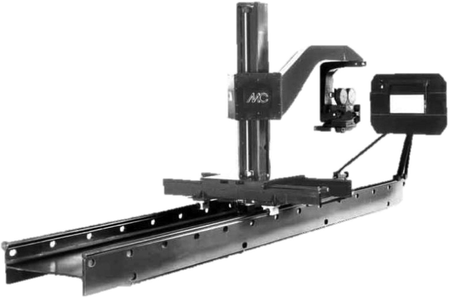
(Above) Similar to system shown above but with our standard four motorized peg bar, neon backlight animation table (see animation stand page) mounted to our standard rotator. The shortened boom arm with vertical offset brings the center of the lens (while in the center of the vertical travel) on center with the rotating table putting everything at a comfortable working height for the operator. Standard model and tabletop work is set up at the opposite end of the track and the boom axis is rotated.
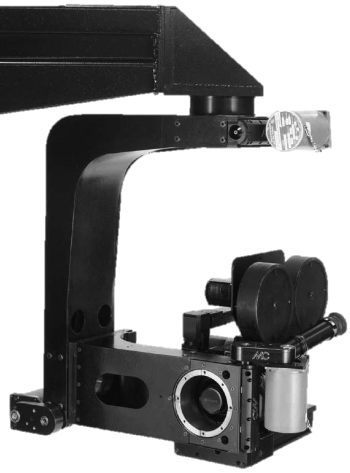
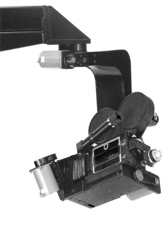
(Above) Standard 360 degree nodal point pan/tilt/ and roll head with standard motorized follow focus base. Shown with Fries (video tap) converted Mitchell camera.
(Above) In this view you can see two screws in the gusset at the front, right hand side of the cradle holding the follow focus base. If you remove those two screws and one more on the other side, the entire follow focus base and camera can be removed from the pan tilt head and used on any standard tripod or head using any one of the multiple industry standard 3/8-16 threaded holes visible in the bottom of the follow focus base.
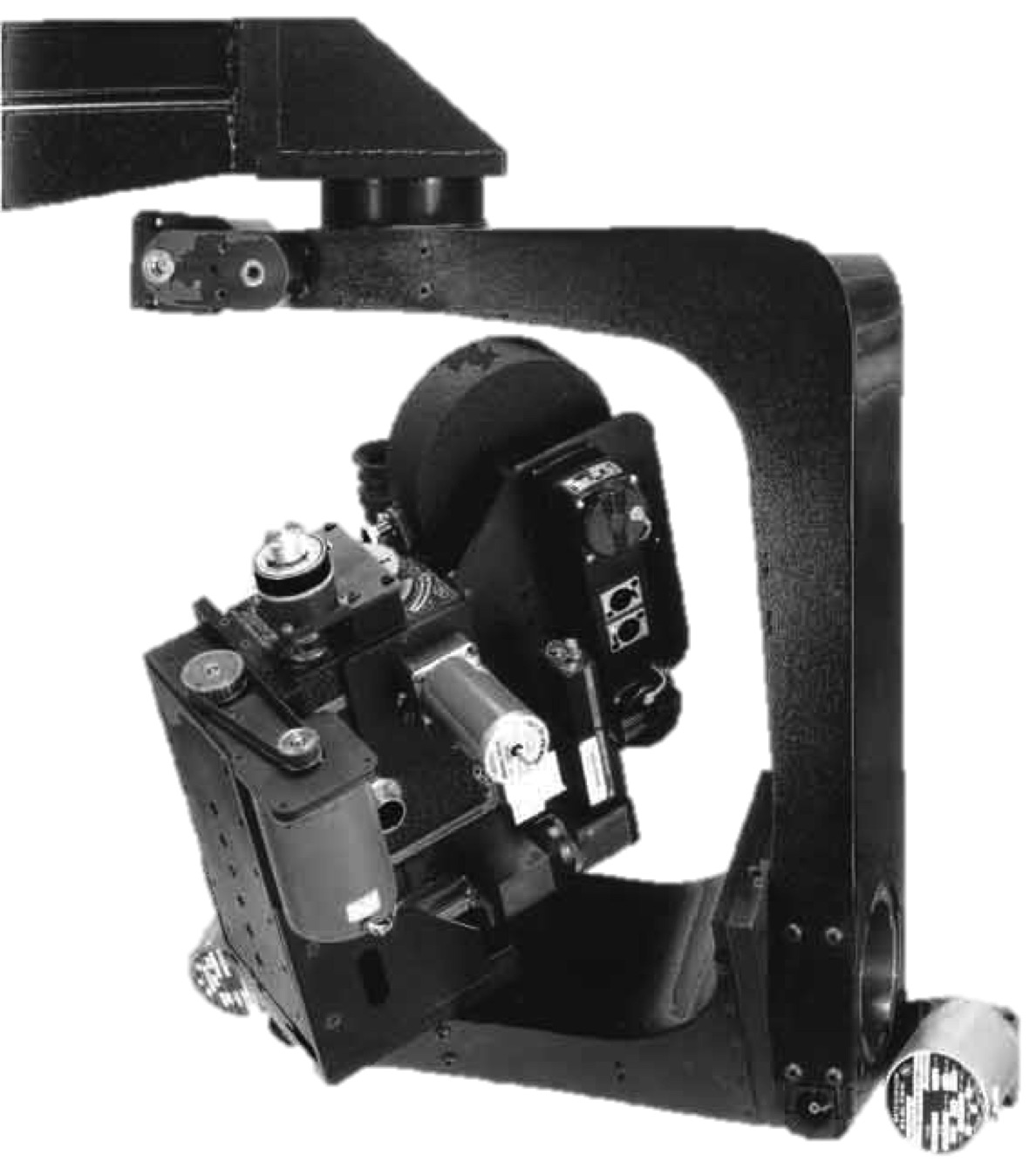
(Above) The other screw that needs to be removed to take the camera/follow focus base out of the cradle is visible at the lower front end of the follow focus base. Also note the keyway on the side of the follow focus base. The keyway provides precise positioning for the camera/follow focus assembly as well as a means to slide the camera/follow focus in and out of the cradle.
The modular nature of these systems makes them infinitely expandable. Because the zoom axis is driven by a precision rack and pinion system, it is possible to have multiple carriages on the same track. These might include an entire separate boom arm system so you could shoot two different shots from each ends of a long track at the same time. It could be a Zoom, North/South - East/West compound with a rotation axis to hold a model.
We also offer a pneumatic counterweight for the main column to provide the ability to add additional load without the need for additional counterweight. You could, for instance, want to mount a model and the lights required to expose it properly that traveled with the camera off of one of the other faces of the cube.
Our Academy Award® winning Rotators are often used in conjunction with these systems.


 "track camera with pan/tilt")
 "track camera with animation table")
 "pan and tilt")
 "pan tilt 2")
 "pan and tilt")